|
I
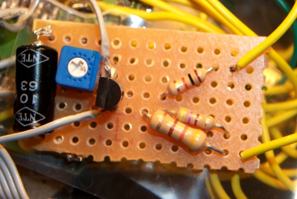
recently modified a toucam
pro 740k per. your instructions. I first tried
the more simplistic modification (I used a
74HC00 NAND gate for the logic) where pins 8 and
13 are linked. I then tried to add an amp switch
per your advanced mod instructions with an
NTE123AP transistor and linked the C-E pins with
a 470 ohm resistor and a 10uf capacitor. During
a long exposure, I received an image where the
top and bottom (horizontal) regions of the CCD
were being exposed for the given long exposure
time, but the middle region was being exposed
for only a short period of time. I then tried a
420 ohm resistor with no more luck than before.
I
thought it was a timing issue, so I assembled
the full blown advanced mod, but it still gave
me the same result. I then placed a POT resistor
that linked the C-E pins. Adjustment
of the pot. allowed
me to find the exact point at which the image
wasn’t garbled and the amp remained in a
relatively off state (you get amp glow at around
200 seconds, but it’s very non-obtrusive. It
nearly triples the exposure length I could have
done before)
In
any case, it turns out that a resistance of
around 200 ohms is more suitable. Perhaps I was
doing something incorrectly, or it could have
been because of the different transistor (but
highly unlikely, I would think), but I thought
others might like to know this if they are
trying to implement this on a toucam
pro. I have found others that have seemingly
done it successfully, though, so I’m not
entirely sure what’s different with my camera
and all the others.
-Mike
Kudenov
|