Main Menu
|

  
The next 2 pages describe the modification
as I initially developed it. Many refinements are possible such as the dead bug method, and track cutting
instead of
pin lifting. Have a look on the which cameras pages for
more info.
If you are about to start work, may I wish
you good luck, and I hope that the next few hours are
fairly stress free!
Its probably best to start with the control logic chips.
Make the circuit below up on a small piece of breadboard.
My thanks to Jim Talbot for the
graphic. Alternatively Ashley Roeckelein's is here
Thanks go to Robert Rolf for adapting the original
circuit to use the 74HC00 and for suggesting static protection on parallel
port lines.
The switch is optional depending on
whether short shutter speeds will be required again
(planetary imaging).
If you would like to test out the logic
for C at this stage it is:-
| |
|
Input A |
| |
|
H |
L |
| Input B |
H |
H |
L |
| L |
H |
H |
Also a connector to the PC's printer port
is needed.
Take a 25 pin male D socket and a length
of 2 core cable (eq loudspeaker cable). The signal lead
is soldered to pin 2 (this goes to lead B on circuit
diagram) and also take a ground eg pin 21. It is probably
a good idea to put a small (eg 2.5 mm) plug on this lead
and a socket on the camera.
|
|
|
|
|
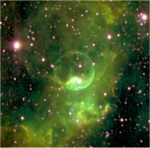
The Poor Meadow Dyke Galleries are now open. THE
GALLERIES |
|
See the full range of Atik cooled CCD cameras for
astronomy on the Atik Website
|
|
|

